|
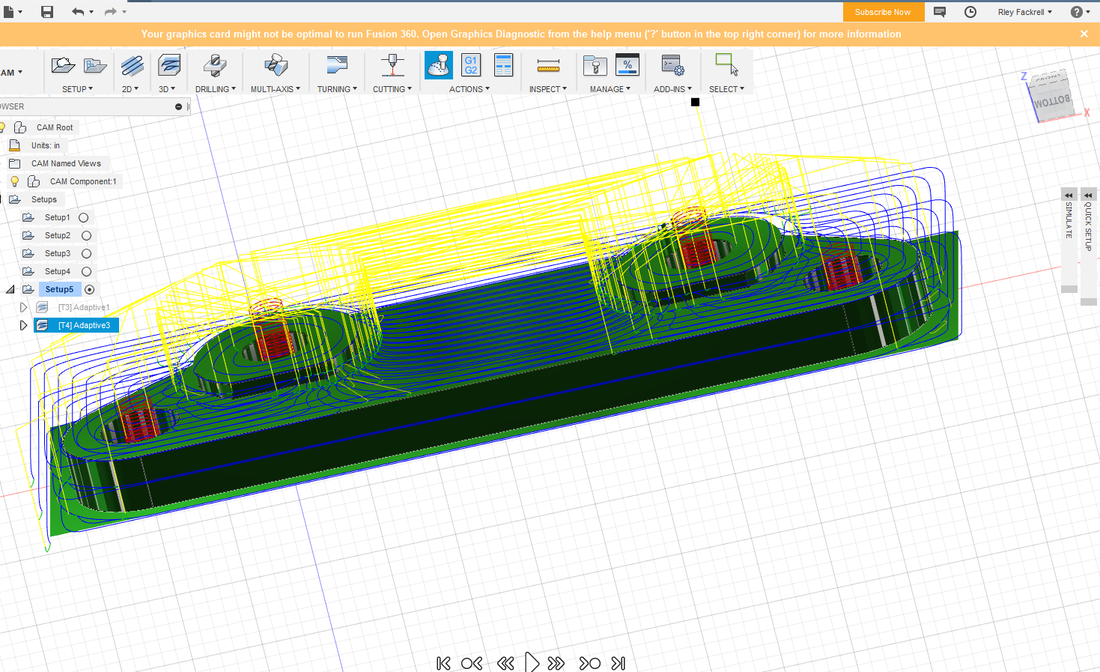
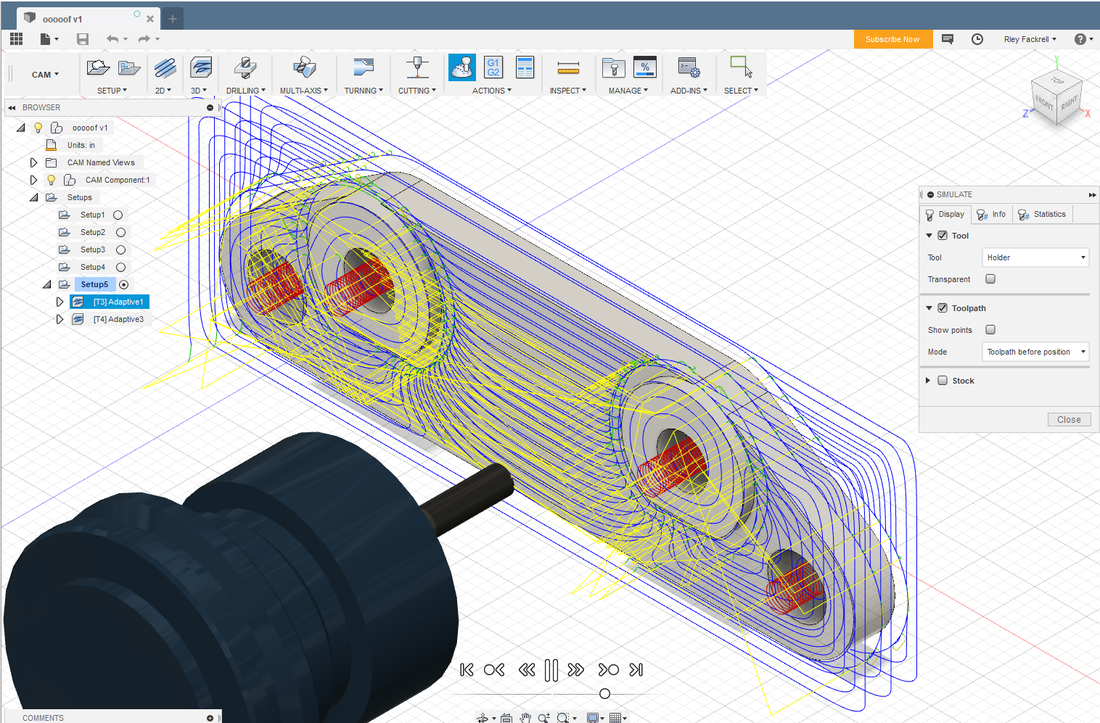
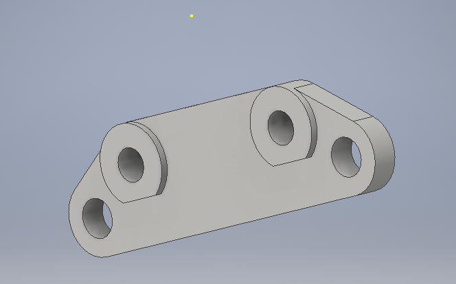
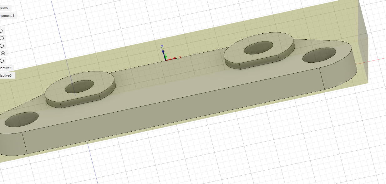
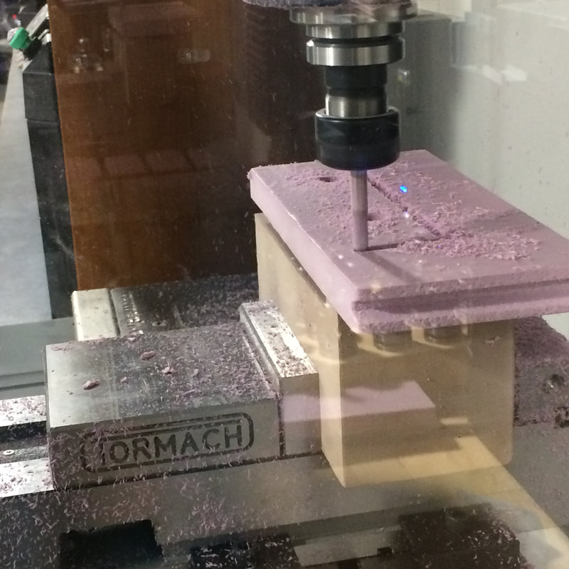
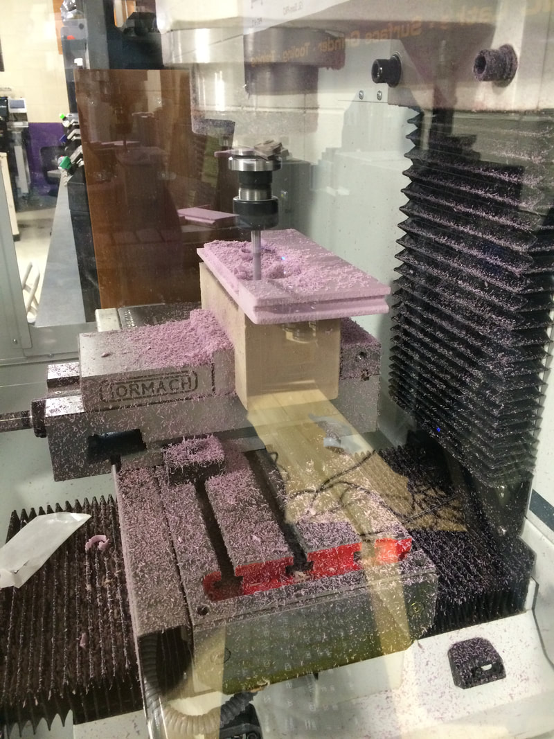
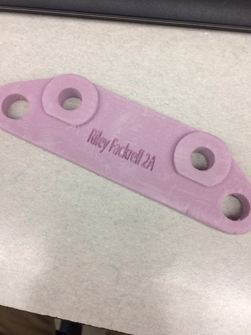
When I got the technical diagram I first decided to model and extrude the outside shape before cutting out holes. I made a rectangle, added circles, and extruded to get the basic shape. After that, I cut out the holes and extruded the larger circles to the proper height. The next step was setting up the toolpath so I turned on the CAM feature, selected 3D adaptive, and changed all the necessary drill and speed settings for the mill. When the path was generated I saved the file as G-code and put it on a flashdrive bound for the mill. At the mill, I opened my code in the software and used the jog pad to position the mill at the bottom left corner of my stock, which I taped onto the base. Once I zeroed the mill and cleared previous settings, I pressed the start button keeping my finger on the space bar in case something catastrophic happened. Fortunately, I didn't have to use the space bar and my brake bracket came out beautifully. The final step was to engrave my name on the bracket. I used the same Illustrator file and laser settings that I used for the maze, and quickly engraved my name on the bracket.
|
|
|
|
|
|
|
I did learn a lot about Inventor considering the fact that there was no shape for 'brake part' in inventor. You sort of had to get creative with the design in order to correctly design the part. Also, I learned that there is a big difference between the router and the mill even though they both use drill bits. Overall, the Mill project was a success, and I would use Mill in the future.
